For many enthusiasts and professionals, learning how to build a tachometer is an exciting and worthwhile endeavor. Whether you are a hobbyist or part of a professional crew responsible for quality assurance in industry settings, this guide will walk you through the tremendous technology involved in crafting your own device.
A tachometer is an essential tool in various fields, especially where precise measurement of rotational speeds is crucial. Understanding its components and working principles is fundamental for building one efficiently.

Understanding the Basics
What is a Tachometer?
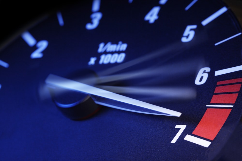
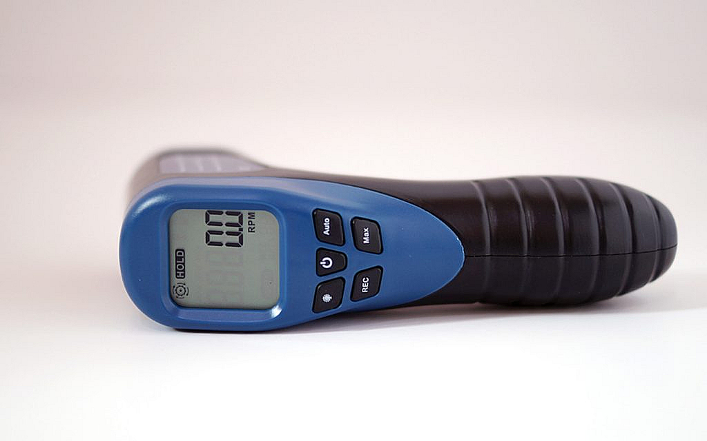
A tachometer is a device used to measure the rotation speed of an object such as an engine shaft or other rotating equipment. It plays a vital role in monitoring and controlling the mechanical performance of machines.
Historical Context
The concept of measuring rotational speed dates back several centuries. Early mechanical tachometers were first used in the late 18th century. With modern advancements, electronic tachometers have now made measurements more precise and reliable.
Building Components
Hardware Requirements
To begin building your own tachometer, youll need the following hardware components:
- Microcontroller (Arduino, Raspberry Pi)
- Sensor (Hall effect sensor, Infrared sensor)
- Display (LED screen, LCD screen)
- Resistors, capacitors, and other electronic components
- Breadboard and wires
Software Tools
Next, you’ll require specific software tools for programming and calibration:
- IDE (Integrated Development Environment)
- Programming language – typically C or Python
Step-by-Step Guide to Building Your Tachometer
Step 1: Setting Up Your Microcontroller
Start by setting up your microcontroller:
- Install the necessary IDE on your computer.
- Connect the microcontroller to your computer and open a new project.
- Write and upload the basic control program to the microcontroller.
Step 2: Connecting the Sensor
The sensor is a critical component as it detects the rotational speed. Follow these steps:
- Connect the power and ground pins of the sensor to the microcontroller.
- Plug the signal output from the sensor to an input pin on the microcontroller.
Step 3: Developing the Software
Next, develop the software to interpret the sensor data:
- Write the code to read the pulses from the sensor.
- Calculate the RPM (Rotations Per Minute) based on the pulse data.
Step 4: Displaying the Results
To display the measurements, follow these steps:
- Connect the display to your microcontroller.
- Write the code to show the RPM on the display screen.
Testing and Calibration
Initial Testing
Run initial tests to ensure that your tachometer works correctly. Check the following:
- If the sensor detects rotation
- If the microcontroller accurately reads pulses
- If the display shows the correct RPM
Calibrating Your Tachometer
Calibrate your tachometer for enhanced accuracy:
- Compare readings with a standardized tachometer
- Adjust the software settings for fine-tuning
Advanced Features
Adding Data Logging Capabilities
To further enhance your tachometer, you can add data logging features:
- Integrate an SD card module with your microcontroller
- Write code to periodically save RPM data
Integrating Wireless Communication
For advanced users, integrating wireless communication is possible:
- Use modules like Bluetooth or Wi-Fi
- Enable remote RPM monitoring on mobile devices
Applications of Tachometers
Automotive Industry
Tachometers are instrumental in the automotive industry where precise engine speed measurement is crucial for performance and safety.
Manufacturing and Quality Assurance
In manufacturing, tachometers are used for monitoring machinery to ensure consistent production quality. Wafer Polishing and Semiconductor Manufacturing benefit from tachometric control.
Health and Safety Applications
In health and safety, tachometers play a role in ensuring equipment operates within safe speed limits to prevent accidents.
Common Challenges and Troubleshooting
Sensor Calibration Issues
Common issues might arise with sensor calibration. Ensure you use reliable components and follow the manufacturers guidelines.
Interference and Noise
Electronic interference and noise can affect tachometer readings. Shield your circuit and use filters to mitigate interference.
Maintenance and Upkeep
Periodic Calibration
Regularly calibrate your tachometer to maintain accuracy.
Component Inspection
Inspect all components periodically to ensure they are functioning correctly. Replace any worn-out parts promptly.
Conclusion
Building a tachometer is a fantastic project for anyone interested in electronics and mechanical engineering. Following these detailed steps will give you a fully functional tachometer that can be used in various applications.
If youre looking for more inspiration, check out these external resources on Wikipedia.

FAQs
Can I use different sensors for my tachometer?
Yes, you can use various sensors such as Hall effect sensors or infrared sensors depending on your needs.
Do I need advanced programming skills?
Basic knowledge of programming languages like C or Python is sufficient to build a basic tachometer.
How accurate is a DIY tachometer?
The accuracy of a DIY tachometer can be quite high if calibrated correctly and built with quality components.
For related projects, take a look at our paint and coating inspection projects and genetic analysis.
